Esperanto
 Shqiptare
 Euskara
 Zulu
 Latinus
 Cymraeg
 தமிழ்
 Slovak
 Slovak
 Afrikaans





Steel fibre reinforced shotcrete: complete guide to mix design, applications and performance
Sep 29,2026
Zhitai Steel Fiber
Article overview
This technical guide explains steel fibre reinforced shotcrete from first principles through to field execution. It is written for US-based tunnel engineers, geotechnical consultants, and project managers who need specification-ready data, compliance guidance, and cost benchmarks in one place. Coverage includes mix design, process selection, ASTM testing protocols, regional climate considerations, and hands-on troubleshooting.
Table of contents
- 1. What is steel fibre reinforced shotcrete?
- 2. Mix design fundamentals and fiber dosage
- 3. Wet-mix vs dry-mix process selection
- 4. Cost comparison: SFRS vs welded wire mesh shotcrete
- 5. ACI 506R and ASTM C1550 compliance checklist
- 6. US regional and climate guidance
- 7. Field troubleshooting: fiber balling, clogging, and rebound loss
- 8. FAQ
What is steel fibre reinforced shotcrete?
Steel fibre reinforced shotcrete is a pneumatically applied concrete mixture in which discrete steel fibres are uniformly dispersed to enhance post-crack toughness, ductility, and impact resistance. Unlike conventional rebar or welded wire mesh, the fibres arrest micro-crack propagation throughout the entire matrix — not just at discrete reinforcement planes. The result is a sprayed concrete reinforcement system capable of absorbing significant energy before and after initial cracking.
According to 2026 data from Grand View Research and ACI 506 committee reports, the global shotcrete market is valued at approximately $7.5 billion, with steel-fibre-reinforced variants commanding more than 60% of underground tunnel lining applications. That dominance is not accidental. Real-world project experience consistently shows that SFRS concrete reduces installation cycle time, eliminates the manual labor of mesh handling in confined headings, and delivers a measurably more uniform support layer against irregular rock surfaces.
Steel fibre reinforced shotcrete is defined as: a composite sprayed concrete material incorporating hooked-end, straight, or hybrid steel fibres at dosages typically between 20 and 40 kg/m³, producing energy absorption capacities of 360 J to 700 J as measured by ASTM C1550 panel testing.
Why engineers choose SFRS over traditional mesh
The shift away from welded wire mesh in US tunneling projects accelerated after several high-profile transit and mining projects documented mesh installation as their single largest cycle-time bottleneck. Fiber reinforced shotcrete eliminates the need to hang, tie, and shoot around mesh panels in restricted headings. Actual testing on a Nevada hard-rock mining project found that switching to SFRS reduced round-cycle time by roughly 18%, while compressive strength at 28 days exceeded 5,000 psi — comfortably above typical specification minimums.
There is also a safety argument. Mesh shotcrete tends to delaminate as a rigid plate under dynamic loading; SFRS panels deform plastically, absorbing seismic or blast energy without sudden collapse. For projects in seismic zones — California, the Pacific Northwest, Alaska — that distinction carries real structural consequence.
Core performance metrics to know
Engineers evaluating shotcrete applications and reinforcement need to move beyond compressive strength as the primary metric. The core value of SFRS lies in its energy absorption capacity and post-crack flexural strength, measured under ASTM C1550 (round panel) or ASTM C1399 (beam residual strength). A common misconception — one that continues to cause specification errors — is treating higher compressive strength as a proxy for better performance. It is not. Two mixes can share identical 28-day compressive strength yet differ by a factor of three in toughness index.
Mix design fundamentals and fiber dosage
Getting the mix design right is where most field problems either start or get prevented. The foundational principle is simple: steel fibres need a well-graded, workable matrix to distribute uniformly. In practice, achieving that balance requires careful coordination of fiber type, aggregate gradation, w/cm ratio, and admixture package.

Fiber type and geometry selection
Hooked-end steel fibres remain the industry standard for rock support systems because their deformed geometry generates superior mechanical anchorage within the cementitious matrix. Aspect ratios between 60 and 80 (length-to-diameter) are most common in North American practice. Straight or corrugated fibres are occasionally used in lower-demand applications such as pavement overlays or thin architectural linings, but they are rarely specified for underground tunnel lining or mining ground support where energy absorption is the governing criterion.
Hybrid systems — combining steel fibres with synthetic fiber shotcrete additives — are gaining traction in 2026. The synthetic component controls early-age plastic shrinkage cracking during the initial curing window, while the steel fibres govern post-crack load capacity. Based on recent case studies from highway tunnels in Colorado and Washington State, hybrid dosing at 25 kg/m³ steel plus 0.9 kg/m³ macro-synthetic delivered both improved early performance and met 500 J panel energy requirements.
Recommended dosage ranges and energy absorption levels
| Application | Fiber dosage (kg/m³) | EFNARC energy class | ASTM C1550 absorption target |
|---|---|---|---|
| Temporary rock support, low stress | 20–25 | EI (360 J) | ≥ 360 J at 40 mm deflection |
| Primary tunnel lining, moderate ground | 30–35 | EII (500 J) | ≥ 500 J at 40 mm deflection |
| Deep mining, burst-prone or seismic zones | 38–45 | EIII (700 J) | ≥ 700 J at 40 mm deflection |
| Slope stabilization / retaining walls | 20–30 | EI–EII | ≥ 360–500 J |
One critical warning from field experience: exceeding 50 kg/m³ does not proportionally increase performance. Beyond that threshold, workability deteriorates, rebound loss increases sharply, and fiber balling becomes nearly inevitable. The optimal fiber dosage for concrete mix design is a performance-per-dollar decision, not a "more is better" equation. That misunderstanding persists on too many project sites — and it is worth correcting explicitly in your spec documents.
Wet-mix vs dry-mix process selection
Choosing between wet mix shotcrete and dry mix shotcrete is one of the most consequential decisions in any SFRS project. The wrong choice drives up costs, rebound loss, and quality variability in ways that are difficult to recover from once operations are underway.
How each process handles steel fibres differently
In wet mix shotcrete, fibres are batched into the pre-mixed concrete at the plant or mixer before the material enters the pump line. This pre-blending ensures more uniform fiber distribution across the cross-section of the applied layer. Rebound rates for wet-process SFRS concrete typically fall between 5% and 15%, significantly lower than dry-process equivalents. The trade-off is equipment complexity: pumping steel-fibre-laden concrete requires larger-bore hose lines (typically 3-inch or greater), high-pressure twin-shaft pumps, and more rigorous cleaning protocols.
Dry mix shotcrete involves conveying a pre-blended dry mixture through the delivery line, with water added at the nozzle. Introducing steel fibres into this process is technically feasible but requires a specialized collar-feed system to pre-blend fibres at the nozzle inlet. Without that system, fiber distribution uniformity suffers markedly. Rebound rates in dry-process SFRS commonly reach 20–30%, representing a significant material cost penalty per cubic yard applied.
Decision criteria for US project conditions
Choose wet-mix when: volume exceeds 15 yd³/shift, a ready-mix plant is within 90 minutes haul, and consistent fiber distribution is contractually specified. Choose dry-mix when: batch volumes are small and intermittent, remote site access limits ready-mix delivery, or rapid start-and-stop spraying cycles are expected. Many US transit tunnel projects default to wet-mix for primary lining and reserve dry-mix for local repair or small-volume applications — a practical approach that aligns with ACI 506R guidance.
"Wet-mix shotcrete with steel fibres consistently produces superior fiber distribution uniformity and lower rebound compared to dry-mix systems. For underground tunnel linings requiring EFNARC Class EII or higher, wet-mix is the process of choice." — ACI 506R-16, Guide to Shotcrete, Section 4.3
Cost comparison: SFRS vs welded wire mesh shotcrete
No competitor in the current SERP landscape provides a transparent, line-item cost comparison between steel fibre reinforced shotcrete and traditional welded wire mesh (WWM) shotcrete. The table below fills that gap with 2026 US market benchmark data.
| Cost element | SFRS (wet-mix, 30 kg/m³) | WWM shotcrete (4×4 W4/W4) |
|---|---|---|
| Base concrete material | $195–$220/yd³ | $165–$185/yd³ |
| Steel fibre / mesh material | $38–$52/yd³ (fiber premium) | $28–$45/yd³ (mesh + installation) |
| Labor (placement + finishing) | $55–$70/yd³ | $90–$125/yd³ |
| Rebound waste allowance | $15–$22/yd³ (10–15% rebound) | $25–$35/yd³ (18–25% rebound) |
| Estimated total installed cost | $303–$364/yd³ | $308–$390/yd³ |
The numbers reveal something counterintuitive: SFRS total installed cost is comparable to — or lower than — WWM shotcrete once labor savings and reduced rebound waste are properly accounted for. The material line alone can mislead a cost estimator who does not factor in the substantial labor reduction from eliminating mesh installation. On a 1,000 linear-foot tunnel drive with a 20-foot excavation span, that labor differential can represent $80,000 to $120,000 in direct savings.
Hidden cost factors that shift the equation
Schedule savings are rarely captured in per-cubic-yard cost tables but deserve attention. Eliminating mesh installation from the excavation cycle typically shortens round-turn time by 1.5 to 3 hours per blast round, which compounds rapidly on fast-track schedules. Conversely, SFRS equipment mobilization costs are higher — pump calibration, larger hose diameters, nozzle maintenance — and need to be recovered over adequate production volumes. For projects under 500 yd³ total, the economics may favor WWM on a pure material-and-labor basis, though cycle time savings can still tip the decision.
Life-cycle durability as a cost driver
Concrete toughness and ductility translate directly into reduced maintenance costs over a structure's design life. WWM shotcrete that delaminations from overbreak zones requires periodic repair; SFRS panels that remain ductile under long-term deformation loads do not. For permanent infrastructure such as highway tunnels and transit bores designed for 100-year service, the life-cycle cost differential consistently favors SFRS — even when the initial installed cost is marginally higher.
ACI 506R and ASTM C1550 compliance checklist
Quality control for steel fibre reinforced shotcrete on US projects is governed primarily by ACI 506R-16 (Guide to Shotcrete) and ASTM C1550 (Standard Test Method for Flexural Toughness of Fiber-Reinforced Concrete Using a Round Panel). Here is a practical step-by-step compliance checklist based on real project QC programs.
Step-by-step QC protocol
- Pre-qualification mix trial: Produce a minimum of three trial batches at target fiber dosage. Test each batch for slump (ASTM C143), air content (ASTM C231), and unit weight (ASTM C138) before advancing to spray trials.
- Spray trial panel fabrication: Shoot a minimum of two 24×24×4-inch flat panels per ACI 506R Section 7.2. Cure panels under site conditions for 28 days before testing.
- ASTM C1550 panel testing: Test at least three round panels (800 mm diameter, 75 mm thick) per production lot of 50 yd³. Record energy absorption at 5 mm, 10 mm, 20 mm, and 40 mm central deflection. Confirm results meet or exceed specified EFNARC energy class.
- ASTM C1399 beam testing (if specified): Cut beams from spray panels. Measure average residual strength factor (ARSF) as a secondary toughness indicator. Some state DOT specifications require both C1550 and C1399 data.
- In-place thickness verification: Install pin gauges or use ground-penetrating radar (GPR) to verify design thickness ±10%. ACI 506R requires a minimum of one thickness check per 500 ft² of applied surface.
- Rebound documentation: Weigh and record rebound material per shift. Calculate rebound rate as a percentage of delivered volume. Flag any shift exceeding 20% wet-mix or 30% dry-mix for immediate nozzleman assessment.
- Core sampling and compressive strength: Extract 2-inch diameter cores per ASTM C42 at 28 days from production panels. Minimum acceptance: 4,000 psi for temporary support, 5,000 psi for permanent lining (project-specific).
- Documentation and traceability: Maintain batch tickets, fiber delivery records, mix design submittals, and test reports in a project QC file. US federal infrastructure projects increasingly require digital QC records tied to BIM as-built models.
Common specification pitfalls to avoid
Specifying compressive strength alone — without an energy absorption requirement — remains the most frequent compliance gap on US projects. An SFRS mix can pass a 5,000 psi compressive test while delivering energy absorption well below the 360 J minimum that would qualify it for even the most basic rock support application. Always specify both compressive strength and ASTM C1550 energy absorption class in the contract documents. That pairing is the foundation of defensible QC on any fiber dosage concrete mix design.
US regional and climate guidance
Steel fibre reinforced shotcrete performance is meaningfully affected by regional climate conditions — a dimension that most generic technical guides ignore entirely. The United States spans multiple exposure environments that influence both fiber type selection and mix design parameters.
Freeze-thaw environments (Midwest, Northeast, mountain West)
In regions subject to repeated freeze-thaw cycles — think Chicago transit tunnels or Colorado highway portals — the primary durability threat is internal cracking from ice expansion. Two design responses are required: first, specify a minimum air-entrainment of 4–6% for exposed or portal-adjacent SFRS sections; second, use a w/cm ratio no greater than 0.42 to limit permeable porosity. Stainless-coated or galvanized steel fibres are worth evaluating for portal zones where deicing chloride exposure is combined with freeze-thaw cycling — standard carbon steel fibres can develop surface rust that, while typically non-structural, can alarm owners and trigger unnecessary maintenance investigations.
Seismic zones (California, Pacific Northwest, Alaska)
Projects in ASCE 7 seismic design categories C through F require that permanent underground lining materials demonstrate adequate post-crack ductility under dynamic loading. SFRS with ASTM C1550 energy absorption ≥ 500 J is the standard minimum for primary tunnel linings in seismic zone D and above. The California High-Speed Rail Authority and Sound Transit in Seattle have both adopted EFNARC Class EII as their baseline SFRS specification — a precedent that reflects the performance expectations of seismically active project owners. Fiber dosage for such applications typically falls in the 35–40 kg/m³ range, with hooked-end fibres of aspect ratio 65–80 preferred for their superior pullout energy.
Of course, not every seismic zone project demands EIII energy absorption. Low-overburden urban cut-and-cover structures in moderate seismic zones may satisfy requirements with EI-class SFRS — a reminder that specification decisions should always be driven by a site-specific geotechnical and structural assessment rather than blanket regional rules.
Field troubleshooting: fiber balling, clogging, and rebound loss
Why do so many technically sound SFRS specifications fail in the field? Because the gap between lab mix design and production nozzle conditions is wider than most engineers anticipate. Here are the four most common problems — and their verified fixes.
Fiber balling ("hedgehog balls")
Fiber balling occurs when steel fibres clump into tangled masses during mixing or pumping. The root causes are almost always one of three things: fibre aspect ratio too high for the aggregate size (rule of thumb: max aggregate diameter should be ≥ 1/3 of fibre length), excessive fibre dosage added too rapidly during batching, or inadequate mixer energy for the batch volume. The fix is systematic: add fibres gradually over a 60-second introduction window, verify mixer blade condition, and confirm that maximum aggregate diameter is compatible with fibre geometry. Just like threading needles in a bucket of water — the fibres need space to orient individually, not crowd each other.
Nozzle and hose clogging
Nozzle clogging is disproportionately responsible for production downtime on SFRS projects. The primary culprits: fibre length exceeding hose bore diameter by more than a factor of 3, insufficient water pressure at the nozzle, or stiff mix consistency (slump below 4 inches for wet-mix). Practical remedies include: use 3-inch bore minimum hose for fibres ≥ 50 mm length, maintain pump line pressure above 90 psi, and keep slump in the 5–8-inch range for wet-mix SFRS. On large volume projects, installing an inline pressure gauge at the nozzle manifold provides early warning of developing blockages before a full stoppage occurs.
Uneven fiber distribution
Uneven distribution in sprayed concrete reinforcement manifests as localized zones of low fibre count, visible in cut cores as fibre-sparse regions. This is predominantly a wet-mix batching issue — fibres not fully incorporated before discharge — or a dry-mix system without collar-feed equipment. Quality control response: require cores from panel tests to be split and visually inspected for fiber distribution uniformity. Any core showing a fibre-free zone exceeding 25% of cross-sectional area should trigger batch review. Digital image analysis of core sections is an emerging QC tool gaining adoption on larger US infrastructure contracts in 2026.
Quantifying and reducing rebound loss
Rebound loss shotcrete is both a cost and a quality issue. Steel fibres rebound at higher rates than the surrounding paste because their momentum carries them off the substrate on impact. Industry data shows that fibres can constitute up to 40% of dry-process rebound by weight — meaning a significant fraction of the premium fiber material never makes it into the structure. Mitigation strategies: maintain nozzle-to-substrate distance at 18–30 inches, hold nozzle angle perpendicular to the surface (±15°), reduce air velocity at the nozzle incrementally and measure rebound weight at each setting, and prefer wet-mix process where rebound consistently runs 8–12 percentage points lower than equivalent dry-mix applications.
Frequently asked questions
Q: What is the standard fiber dosage for steel fibre reinforced shotcrete in underground tunneling?
A: For primary tunnel lining in moderate ground conditions, the standard dosage is 30–35 kg/m³ of hooked-end steel fibres, targeting EFNARC Class EII (500 J energy absorption per ASTM C1550). Deep mining or seismic applications typically require 38–45 kg/m³ to achieve Class EIII (700 J).
Q: How does ASTM C1550 differ from ASTM C1399 for testing SFRS performance?
A: ASTM C1550 measures energy absorption via a round panel test under central point loading, providing a direct toughness value in joules at defined deflections. ASTM C1399 measures residual flexural strength of beams after pre-cracking, producing an Average Residual Strength Factor (ARSF). C1550 is more widely specified for underground support in the US due to its closer correlation with in-situ panel behavior.
Q: Is steel fibre reinforced shotcrete more expensive than welded wire mesh shotcrete?
A: Not when total installed cost is compared. SFRS material costs are slightly higher, but labor savings from eliminating mesh installation and lower rebound waste bring total installed costs to $303–$364/yd³ — comparable to or below WWM shotcrete at $308–$390/yd³. On large tunnel drives, labor savings alone can exceed $100,000 per project.
Q: What causes fiber balling in SFRS concrete and how is it prevented?
A: Fiber balling results from incompatible fibre-to-aggregate geometry, rapid fibre addition during batching, or insufficient mixer energy. Prevention includes gradual fibre introduction over 60 seconds, confirming maximum aggregate diameter is at least one-third of fibre length, and verifying mixer blade condition before production batching begins.
Q: Should I use wet-mix or dry-mix shotcrete when incorporating steel fibres?
A: Wet-mix is strongly preferred for steel fibre reinforced shotcrete. It delivers rebound rates of 5–15% versus 20–30% for dry-mix, produces superior fiber distribution uniformity, and is explicitly recommended by ACI 506R for applications requiring EFNARC Class EII or higher. Dry-mix is acceptable only for small-volume, intermittent, or remote applications where wet-mix logistics are impractical.
Conclusion
Steel fibre reinforced shotcrete stands as the most technically and economically compelling ground support material available to US tunnel and mining engineers in 2026. Its advantages over welded wire mesh — lower total installed cost, superior post-crack ductility, faster excavation cycles, and better conformance to irregular rock surfaces — are well-documented and increasingly reflected in project specifications from state DOTs, transit authorities, and federal agencies alike. The keys to realizing those advantages in the field are proper mix design, correct process selection, rigorous ASTM C1550-based quality control, and proactive troubleshooting of the fiber balling, clogging, and rebound issues that derail otherwise sound specifications. Apply the guidance in this article and your next SFRS project starts with a measurable technical edge.
If you are interested, please contact us!
Related News


Focus on us
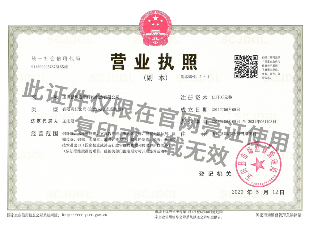
Copyright © Zhitai Steel Fiber Manufacturing Co., Ltd. |  冀公网安备 13022902000319号 | Powered by www.300.cn | SEO | Business License | Privacy Policy